Glory Info About How To Generate A Netlist

How To Generate NETlist In Altium Designer YouTube
Unlocking the Secrets of Netlist Generation
1. What Even Is a Netlist? And Why Should I Care?
Ever wondered how that beautiful schematic you painstakingly drew on your computer actually transforms into a physical circuit board? Well, my friend, the unsung hero in that process is the netlist. Think of it as a detailed recipe that tells the manufacturing machines exactly which components to connect to which pins. It's the bridge between your design and the real world, the translator that speaks both engineer and machine.
Without a netlist, your design would just be a pretty picture. It's the crucial file that outlines all the components in your circuit and, more importantly, how theyre all interconnected. Imagine trying to bake a cake without a recipe — you might get something edible, but it probably won't be what you intended. The netlist prevents similar chaos in circuit board creation.
So, if youre designing anything more complex than a simple LED circuit, understanding netlists becomes incredibly important. It's not just for seasoned professionals either; hobbyists and students can greatly benefit from learning the ropes. It will save you headaches, wasted prototypes, and a whole lot of frustration.
This is more than just understanding a file format; it's about comprehending the fundamental language used to bring your electronic creations to life. Think of it as learning a new dialect so you can speak directly to the machines! Pretty cool, right?

The Journey Begins
2. Schematic Integrity
Before you can even think about generating a netlist, your schematic needs to be in tip-top shape. A sloppy schematic leads to a faulty netlist, and that, in turn, leads to a board that doesn't work as intended. Garbage in, garbage out, as they say.
First, double-check that all your components are correctly placed and oriented. Polarity matters! Then, scrutinize every connection. Are all the wires actually connected to the right pins? Are there any dangling wires or unintended shorts? These are the kinds of gremlins that love to hide in your designs and wreak havoc later on.
Another important step is to ensure that each component has a unique identifier, often called a reference designator (like R1, C2, U3). These identifiers are crucial for the netlist to correctly map the components in your schematic to the physical parts on the board. Without them, the netlist will be a jumbled mess.
Finally, take a deep breath, zoom in on your schematic, and visually inspect every inch. It's like proofreading a document before submitting it — catch those mistakes before they become bigger problems. Believe me, a little preventative care here goes a long way!

Generating the Netlist
3. Choosing the Right Tool for the Job
Okay, so your schematic is immaculate and ready to go. Now comes the moment you've been waiting for: actually generating the netlist. Fortunately, you dont have to do this by hand (unless youre a glutton for punishment). Your Electronic Design Automation (EDA) software will handle the heavy lifting.
Most EDA tools (like KiCad, Eagle, Altium Designer, etc.) have a built-in feature for netlist generation. The exact steps might vary slightly depending on the software you're using, but the general process is usually pretty straightforward. Look for an option labeled "Generate Netlist," "Export Netlist," or something similar.
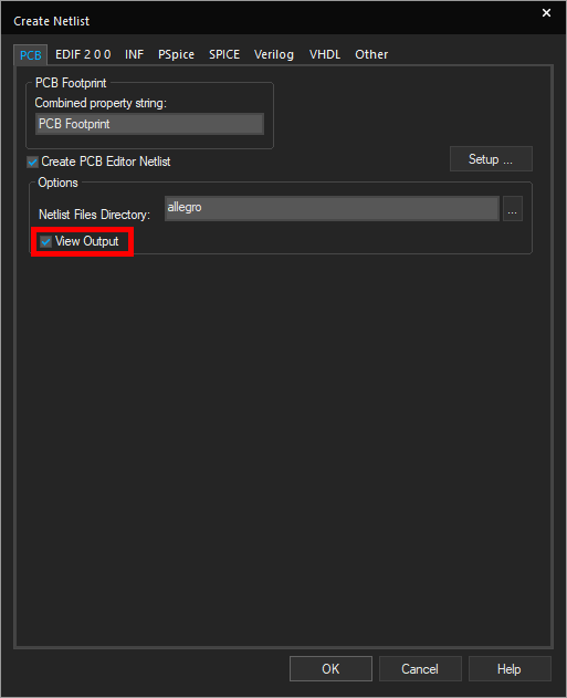
Before clicking that button, you might be presented with a few options. Pay attention to the netlist format. Common formats include Allegro, PADS, and standard formats like Gerber. The choice depends on what your PCB manufacturer or other software expects. If youre unsure, consult their documentation or ask for clarification.
Once you've selected the appropriate settings, hit that generate button! The software will then churn through your schematic and produce a netlist file, typically with a `.net` or `.lst` extension. Congratulations, youve officially created your netlist! But the adventure doesnt stop here

How To Netlist A Design In OrCAD Capture EMA Automation
Decoding the Netlist
4. Understanding the Language of Connections
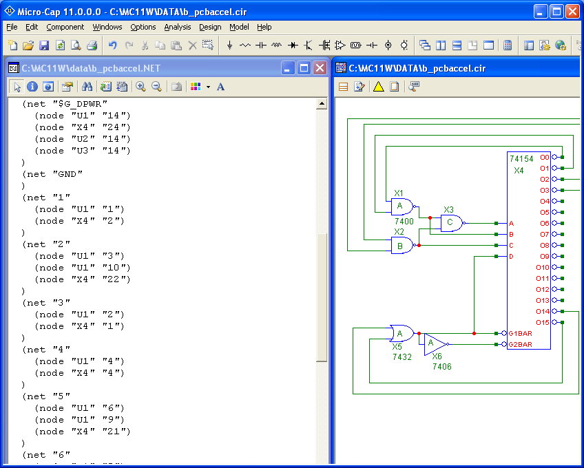
Alright, you have a netlist file. Now what? While you don't need to become fluent in netlist syntax, it's helpful to understand the basic structure. Open the file in a text editor (Notepad or similar) and take a peek.
You'll likely see a list of components and their connections. Each line typically describes a connection between two or more pins. The format can vary depending on the netlist type, but you'll usually find component names, pin numbers, and net names.
For example, you might see something like: `R1 1 N$1; C1 1 N$1;`. This indicates that resistor R1, pin 1, is connected to capacitor C1, pin 1, on a net labeled "N$1." These connections are the essence of your circuits functionality, described in a format a computer can understand.
Dont be intimidated by the seemingly cryptic language. The main takeaway is that the netlist is simply a text file that meticulously describes the connections in your schematic. Understanding this basic principle will make it much easier to troubleshoot any problems that might arise during the PCB layout or manufacturing process.

How To Generate SPICE Netlist Ltspice YouTube
Troubleshooting Common Netlist Issues
5. When Things Go Wrong (and They Often Do)
Even with the best intentions, things can sometimes go wrong during netlist generation. Fortunately, most problems are relatively easy to fix, as long as you know where to look. One common issue is "unconnected pins." This usually means that a wire in your schematic isn't properly connected to a component pin.
Another frequent culprit is missing or duplicate component identifiers. Make sure that every component has a unique reference designator and that you haven't accidentally used the same identifier for multiple components. This is especially important when you copy and paste sections of your schematic.
Sometimes, the netlist generation process itself can produce errors. If this happens, try updating your EDA software to the latest version. Software updates often include bug fixes and improvements that can resolve netlist generation issues.
The best way to troubleshoot netlist problems is to carefully compare the netlist file to your schematic. Look for discrepancies in component connections or identifiers. A methodical approach is the key to quickly identifying and resolving these issues. A little patience and attention to detail can save you a lot of headaches down the road.

How To Generate A Netlist In OrCAD Capture 17.4 YouTube
From Netlist to PCB
6. The Beginning of the Physical Realm
Generating the netlist is just one step in the journey from concept to completed circuit board. With your netlist in hand, youre ready to move on to the next phase: PCB layout. This involves arranging the components on the board and routing the traces to connect them according to the netlist.
During PCB layout, you'll use your EDA software to place components, define board dimensions, and create copper traces that connect the components according to the instructions within the netlist. The netlist guides the layout process, ensuring that all the correct connections are made.
After the layout is complete, you'll generate Gerber files, which are used by PCB manufacturers to fabricate your board. These files contain all the information needed to create the physical circuit board, including the copper layers, solder mask, and silkscreen.
So, remember, the netlist is not the end of the line, but rather a crucial stepping stone towards bringing your electronic designs to life. Its the foundation upon which your physical circuit board is built.